Table of Contents
Suspension
As described in Z1 history, the powertrain and chassis of the Z1 were largely E30 components, an aluminium tube ran from the gearbox to the differential. A multi-link axle comprising two transverse control arms and one longitudinal control arm, dubbed the “Z-axle”, shorthand for “centrally guided, spherical double-wishbone axle” rather than a reference to the new model’s name. The kinematic arrangement of the three control arms ensured excellent directional stability as well as effective anti-squat and anti-dive, endowed the Z1 with go-kart-like handling, with the axle load split in the ratio 49:51 and the vehicle’s centre of gravity located some ten centimetres lower than on comparable models, what the Z1 lacked in power it more than made up for it in handling.
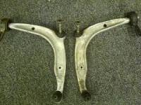
However the axle arrangement was not standardised across all cars, with a mix of Aluminium and Steel on the Front control arms and rear Z-shaped trailing arms. Aluminium arms are lighter without the camber adjustment, whereas the Steel arms retain the camber adjustment and can be adjusted. The Steel arms allow the fitment of modern floating and vented disks owing to the caliper position and are better for upgrading the rear brakes and allow for bigger wheels as there is more space under the arch.
- AL0001 - AL01541: Steel Front Axle, Aluminium rear Axle
- ALO1541 - AL05254: Aluminium Front and Aluminium rear
- ALO5254 - ALO8000: Aluminium Front and Steel rear
The track is the same on the old and new suspension, the difference is the drive shaft length, the hubs and the arms, the older setup has shorter “wishbones” and drive shafts with taller hubs. Aftermarket upgrades are easier on the newer arms such as H+R Coilovers. The older setup is lighter and reduced unsprung weight with the front and rear coilovers.
BMW M3 E30 Auminium Lower wishbones front arms, a common upgrade to lower the unsprung weight.
The difference is noticeable by the rear brake setup, the Calipers on the earlier cars sit at the front of the wheel, whereas the later cars they sit to the rear of the wheel.
Alignment
4 wheel Alignment is critical to preserve your car’s safety and tyre wear, it ensures all your wheels are consistent and optimized for maximum road surface contact and this is configured by three components, Camber, Caster and Toe.
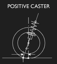
Caster
This is the angle created by the steerings pivot point from the front to back of the vehicle. Caster is positive if the line is angled forward, and negative if backward. Typically, positive caster will make the vehicle more stable at high speeds, and will increase tyre lean when cornering.
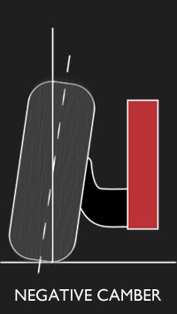
Camber
Camber angle is the difference between the wheels vertical alignment perpendicular to the surface, so a wheel perfectly perpendicular to the surface, its Camber angle would be 0 degrees.
Toe
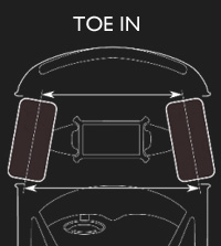
This represents the angle derived from pointing the tyres inward or outward from a top-down view – much like looking down at your toes and angling them inward or outward.
Correct toe is paramount to even tread wear and tyre life. Either inward or outward, they will scrub against the surface of the road and cause wear along the edges. Depending on usage, tread life is sacrificed in favour of performance or stability.
Positive toe occurs when the front of both tyres begins to face each other, permitting both wheels to generate force against each other, this reduces turning ability, but creates straighter driving characteristics.
The Z1 is adjusted from back to front, Caster, Camber, then Toe. In order to adjust the rear suspension during a 4 wheel alignment, the side panel must be removed.
Readout
From a standard 1989 Z1 after a 4 wheel alignment check.
After / (Before)
- LF Camber - N/A
- RF Camber - N/A
- LF Toe 0.07 (0.40)
- RF Toe -0.07 (0.40)
- LR Camber -1.27 (-1.41)
- RR camber -1.12 (0.58)
- LR Toe 0.04 (0.02)
- RR Toe 0.13 (0.12)
- Front total Toe 0.15 (1.32)
- Front steer ahead 0.00 (-0.02)
- Rear Total toe 0.16 (0.14)
- Rear thrust angle -0.04 (-0.05)
Steering Shudder
Steering shudder occurs on most cars over time, occurring when just ambling along a rocky road or under braking. Attributed to a combination of things such as anti roll-bar bush, rear wishbone bush, tyres, warped brake discs or wheels, calipers, steering rack universal joint, tie rod ends, but one of the little known causes is the steering column shaft. The play is between the fixed lower section of the column and the moveable upper section of the column, there is a collar nut that tightens the female splined shaft onto the male splined shaft. You can get some idea of what things look like here:
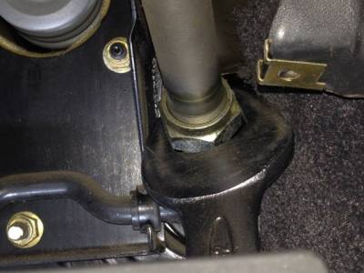
It's the large 32mm nut on the shaft in the lower part of the diagram, the play between the shaft shows up as a rattle in the steering wheel, made worse by any wheel imbalance or other play in suspension bushes.
Located just above the accelerator pedal, this adjustment also impact your steering adjustable 'reach'.
Start by getting a feel for the presence of the play and the amount of effort required to change the steering column's reach. Tightening the nut will reduce/eliminate the play and will also increase the effort required to change the reach and will eventually prevent the reach from being adjusted altogether.
Remove the trim panel under the column by undoing the screws and the plastic quarter turn fastener. Place the 32mm spanner on the nut and turn the steering wheel clockwise by half a turn while holding the spanner in place. Remove the spanner, straighten out the wheel and check for a reduction in the play and/or a change in effort needed to adjust the reach. Repeat this tightening sequence either a half or a quarter turn at a time until the play is gone and hopefully you still have some reach adjustment, you ideally want to find the balance between reduced play and reach is adjustable.
It may be easier to have the engine running, using the power steering to help turn the wheel. When you think you've found that balance, take the car for a drive and see if you notice the change.
Here are some visuals to aid adjustment, the first image is of the 32mm nut above the accelerator pedal.

