Table of Contents
Bodywork
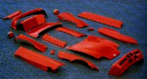
The Z1 is equipped with a front and rear reversible bumper safety system, in speeds up to 2.5MPH at maximum impact angles of 30deg, no damage will occur as the elasticity of the panels will mitigate this, flexing between 40-45-mm. This was highlighted at the launch by the then Director Ulrich Bez, who gave a demonstration of the benefits of the plastic panelling, he jumped with both feet onto a vehicle wing lying on the floor, which promptly buckled and sprang back to its original shape when he stepped off, the side panels were also integral in impact protection.
The Bumper system was developed in collaboration with MBB and assembled by coachbuilder Bauer, it consists of a highly elastic thermoplastic made skin with reinforced fibreglass (GRP), plastic support rings and fibreglasss springs as a damper. The front indicators are integrated into the front bumper and protected against collision damage. The steel monocoque had especially strong side sills to compensate the loss of roof. Furthermore, the composite undertray and the strong torque tube (linking between the transmission and the rear differential) also strengthened the chassis.
Front Bumper Removal
Level: Easy
REMOVING AND INSTALLING FRONT PANEL
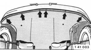
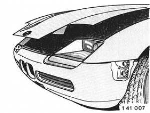
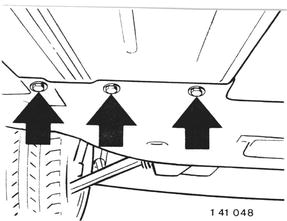
Unlock engine hood. Unscrew bottom panel screws.
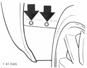
Unscrew front screws of wheel house cover.
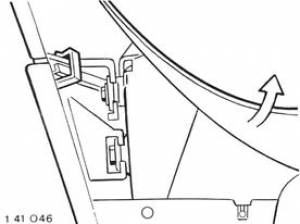
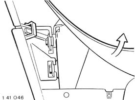
Pull up wheel house cover and pull off clips.
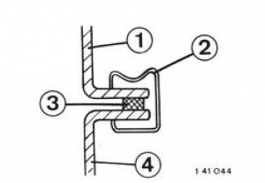
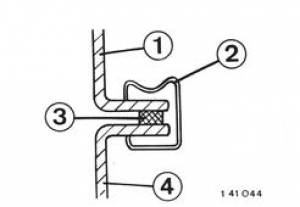
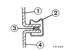
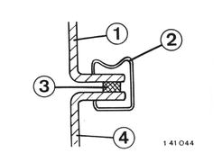
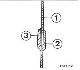
Installation: The flat side of clip (2) faces down.
1 Side panel 2 Clip 3 Rubber seal 4 Front or tail panel
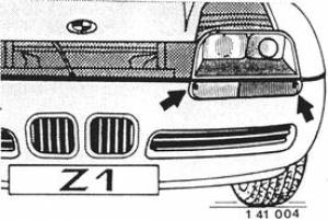
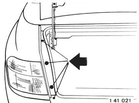
Unscrew lenses of left and right turn signals. Take off rubber seals. Pull off center rubber seal (cemented).
Installation: Replace center rubber seal (self- adhesive). Left/right rubber seals are held by the turn signal lenses. Check for correct seating of rubber seals between headlights and turn signals.
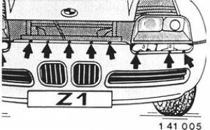
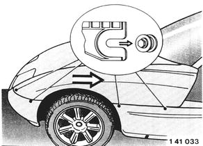
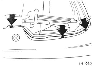
Unscrew screws. Knock out plugs in clips toward the inside. Lift out clips from above.
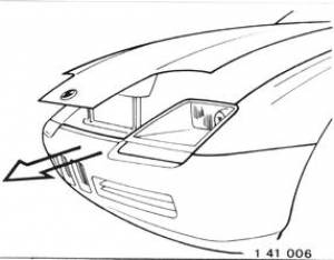
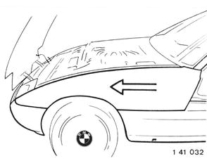
Lift off front panel forward.
Tip: Slide Bumper onto soft surface Tip2: Check front kidney grills are firmly in place, re-fit with double sided pads.
Installation: Slide guides into rubber mounts on left and right sides. Check for correct seating of wheel house trim panels.
Rear Bumper Removal
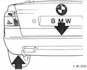
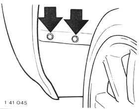
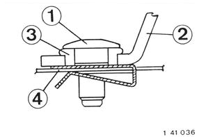
Unscrew bolts.
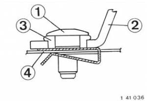
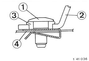
Installation: 1 Bolt 2 Outer body panel 3 Rubber grommet - don´t displace while tightening bolt (1) 4 Chassis
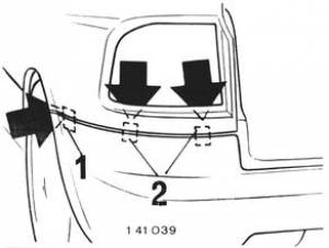
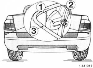
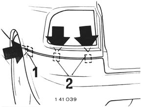
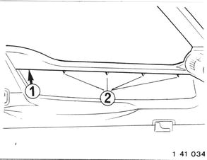
Pull off clip (1) from the wheel house and clips (2) from the tail light opening.
Installation: The flat side of clip (2) faces down.
1 Side panel 2 Clip 3 Rubber seal 4 Front or tail panel
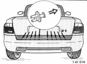
Pull plugs out of expansion rivets with a nippers or side cutter. Pull out expansion rivets from above. Pull back rubber mounts out of the tail panel.
Installation: Coat rubber mount (2) with a rubber lubricant. Install tail panel by sliding guides (1) into rubber mounts (2). Check for correct seating of seals (3) to mating parts.
Installation: Check for correct seating of bottom retainers. Press on tail panel until retainers engage.
Front Wing Removal
REMOVING AND INSTALLING LEFT/RIGHT FRONT SIDE PANEL
Unscrew front screw of wheel house cover.
Lift up wheel house cover and pull off clips.
Installation: The flat side of clip (2) faces down.
1 Side panel 2 Clip 3 Rubber seal 4 Front or tail panel
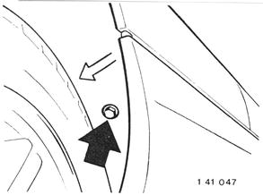
Unscrew screws.
Installation: 1 Bolt 2 Outer body panel 3 Rubber grommet - don´t displace while tightening bolt (1) 4 Chassis
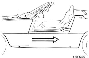
Pull side panel forward and lift off.
Installation: Coat rubber mount with a rubber lubricant. Install side panel by sliding guides into the rubber mounts. Check for correct seating of seals to mating parts.
Side Panel Removal
Unscrew screw of front wheel house panel. Lift front wheel house panel over edge of the side panel.
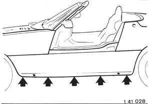
Unscrew screws.
Unscrew screws of engine compartment splash guard.
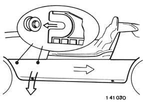
Counterhold on guides of the middle side panel. Pull out bottom of side panel over the car jack take-up.
Caution! Guides could tear out when expansion is excessive.
Pull back side panel out of the rubber mounts and lift off side panel.
Installation: Coat rubber mounts with a rubber lubricant. Install side panel by sliding guides into the rubber mounts. Check for correct seating of seals to the mating parts.
Rear Quarter Removal
Remove tail light assembly
Right Side: Take off tank cap. Install tank cap again after removal of the side panel - danger of fire from escaping gasoline vapors.
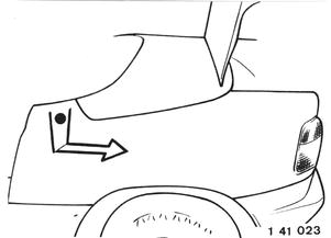
Shut trunk lid. Raise top lid. Unscrew screws.
Pull off clip (1) from the wheel house and clips (2) from the tail light opening.
Installation: The flat side of clip (2) faces down.
1 Side panel 2 Clip 3 Rubber seal 4 Front or tail panel
Unscrew screws - counterhold on nuts.
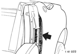
Open door. Push brush aside and unsrew bolt.
Installation:@L 1 Bolt 2 Outer body panel 3 Rubber grommet - don´t displace while tightening bolt (1) 4 Chassis
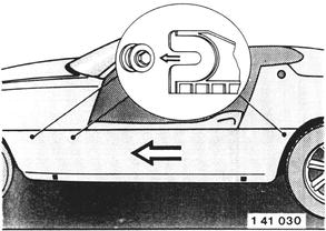
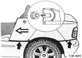
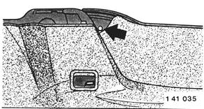
Pull out side panel at top over the door lock and then pull back out of the rubber mounts.
Installation: Coat rubber mounts with a rubber lubricant. Install side panel by sliding the guides into the rubber mounts. Check for correct seating of seals to the mating parts.
Installation: Insert rubber seal (2) for the door lock in side panel (1) and push on retainer (3).
Door Skin Removal
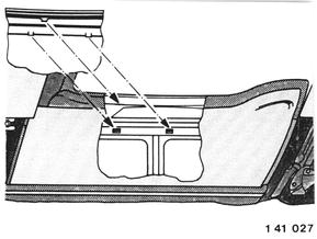
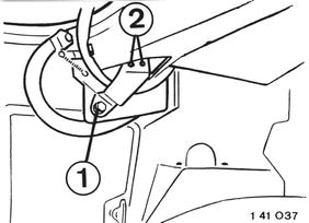
Lower door window completely. Remove middle side panel - see 41 35. Lower door manually about 150 mm (6”). Unscrew screws (2). Only loosen screw (1). Remove door trim panel - see 51 41.
Unscrew screw through hole.
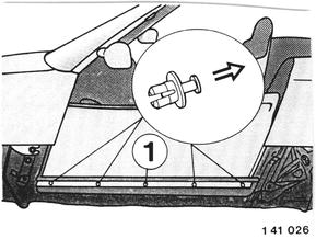
Pull plug out of expansion rivet with a snippers or side cutter and pull out the expansion rivet. Unscrew screw (1). Lift out outer door panel from above.
Installation: Attach the four hooks of the top row on the outer door panel on the upright sheet metal edge. Attach the five hooks of the bottom row in openings on the door body.
Click Door Skin for further instructions.
Bonnet Removal
Loosen hose clamps and straps. Disconnect plugs. Pull off hoses. Unscrew bolts.
Installation: Replace worn hose clamps and straps. Replace stopnut.
Aligning Bonnet
Loosen bolts. Screw in stop pads.
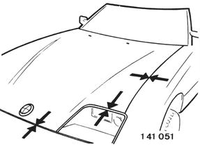
Align bonnet with the side panels, front panel and headlights. Tighten bolts.
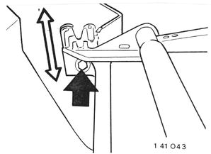
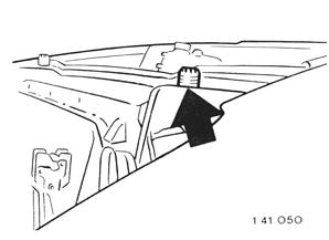
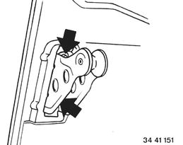
Align height at front end of the bonnet by adjusting the lock. Adjust the bonnet in height that the engine hood is about 1 mm (0.039”) deeper than the side panels.
Note: View of lock from the right.
After adjusting unscrew the stop pads far enough that the bonnet is preloaded slightly and positioned in one plane with the side panels.
Note: The left headlight is removed in the picture for a better view.
Adjusting Rear Guide Roller:
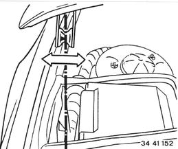
Loosen bolts.
Adjust holder laterally until the guide roller slides into the catch perfectly. Check the gap between the side panel and bonnet on left and right sides.
Adjusting Rear Bonnet Height:
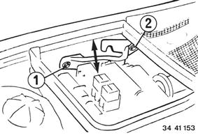
Loosen bolts (1 and 2). Adjust catch on bolt (2) in such a manner that a closed bonnet is level with the side panels.
Note: The deeper the lock, the further forward the bonnet.
Boot Removal
Aligning Boot
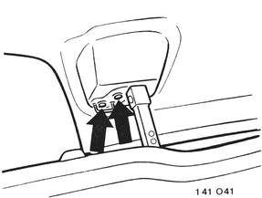
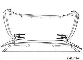
Loosen boot screws.
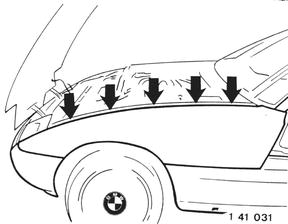
Align boot with side panels and top storage box lid. Tighten boot screws.
Height of boot to top storage box lid is aligned with the marked screws. Boot should be approx. 1 mm deeper than the convertible top storage box lid.
Loosen screws of boot lockplate. Adjust lock plate until there are equally wide gaps to the side panels and top storage box lid. Boot should be approx. 1mm deeper than the convertible top storage box lid. Tighten screws.
Boot Lid
Align Boot Lid
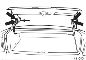
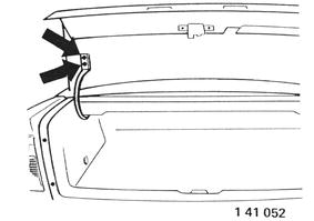
- Loosen screws of Boot lid.
- Align Boot lid with side panels and Boot.
- Tighten screws.
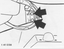
Adjust height of Boot lid with screw (1). Top Boot lid should be approx 1 mm higher than the Boot.
2 = Boot lid hinge
- Remove trim panels on left and right B-pillars.
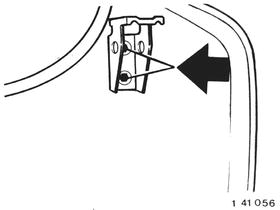
- Loosen screws and adjust locks on both sides.
- Loosen screws and adjust lock shackle.
Cowl removal
Remove outside mirror, Unscrew screws and take off panel.
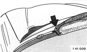
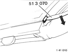
Lift ornamental frame out of clip with Special Tool.
Lift ornamental frame out of clips from top to bottom. Take off ornamental frame.
Pull off guide (1). Lift panel on outside and remove.
Indicators
UK law states that side indicators are required for all cars manufactured after 01.Jan.1986
Repairs
REPAIRING COMPOSITE FIBER MATERIAL COMPONENTS
FLOOR/HOOD/LID
Repairs can only be carried out correctly with approved repairing materials
Basic equipment repair it (available from Cartool) Material repair kit (available form BMW Parts)
and strict conformance with the discribed procedures. Repairs are described in details in the SIP film “Repairing Composite Fiber Material Components (Floor Plate and Hood/Lids) on Z1”.
Stripped threads of threaded inserts in the car´s floor plate can be repaired by installing helicoil inserts - refer to SI 41 03 90 (178).
When repairing the floor and hood/lids (glass fiber/epoxid sandwich) a difference must be made between
Surface Scratches
Repaired to paintwork instructions in Repair Manual.
Deep Scratches
Refer to safety precautions on page 41-00/2.
Uncover damaged spot enough until undamaged layers are accessible. Clean damaged spot generously with rags soaked in acetone; wipe dry afterwards. Determine actual size of damage. Knock on surface around damaged spot 20 cm away with a hard item (e.g. screwdriver) to find invisible separation of top layer laminate from the foam core. Insufficient adhesion can be noticed by the difference in sound.
- Important!
If hood/lids are damaged, knock around the damaged spot on the inside and outside!
Mark actual size of damage. Check whether reapring is possible (refer to concerned repair zone).
Grind off top layer laminate (1) with a angle grinder fitted with a soft sanding disc, grain size 60 to 80, in such a manner that the foam core (3) plus an additional 10 mm around the damaged spot is visible. Taper edges with an eccentric grinder, grain size 80 to 100. Taper length “L” is removed from ground glass fiber material (2).
- Floor:
2 layers, L = 30 to 40 mm 4 layers, L = 40 to 50 mm
- Hood/Lids:
L = 35 to 45 mm
Transfer size of damaged spot to polyester sheet (50 x 50 cm) with a water proof pencil to scale of 1 : 1; add 1 cm all around.
Damage Repair 1
REPAIRING HOLES, CRACKS, CHAFINGS AND DELAMINATIONS OF ONE DAMAGED TOP LAYER
Refer to safety precautions on page 41-00/2! Foam core will have to be replaced, if there are holes or chafings deeper that 3 mm.
- Only for replacement of foam core, cut out foam core around the damaged spot in rectangular shape with a carpet knife and remove foam core with a mortise chisel.
- Extract or blow off abrasion from damaged spot.
- Only for replacement of foam core, cut new piece of foam from repair kit to size and fit in (gap size not larger than 3 mm).
- Clean taper with clean, acetone-soaked rags; wipe dry afterwards.
- Don´t clean the foam surface; danger of absorption!
-Air dry at least 15 minutes.
- Cut all glass fiber tissue layers to size of damaged spot.
- Orientate tissue as in the original component; refer to picture of concerned repair zone for number of layers.
- Cut perforated sheet to size of damaged spot plus about 2 cm.
- Cut absorption fleece to size.
- Prepare vacuum sheet.
-Paste on vacuum sealing tape; watch out for size of heating blanket. Don´t pull off the protective sheet!
- Place perforated sheet on polyester sheet.
-Mix epoxy resin and epoxy thick sheet.
- Place first layer of glass fiber tissue on perforated sheet and soak with epoxy resin until white spots are no longer visible.
- Position other layers of glass fiber tissue and soak each layer thoroughly with epoxy resin; don´t use too much resin.
- Only for replacement of foam core, install foam core with thick resign.
-Brush in damaged spot with thick resin; eliminate small irregularties and holes in foam core with thick resin.
- Lift repair laminate with perforated sheet off of polyester sheet, place on repair surface and press on firmly. Important! Perforated sheet must be on outside.
- Install absorption fleece, heating blanket and absorption fleece to the vacuum assembly on page 41-00/10.
- Pull protective sheet off of vacuum sealing tape; press on and seal vacuum sheet.
- Switch on vacuum pump; produce seal by pressing vacuum sheet on vacuum sealing tape.
- Hardening Repaired Surface: Normal hardening 12 hours are room temperature (more than 20° C) possibly overnight or fast hardening 3 hours at 60° C with help of heating blanket. Always temper 1 hour at 120° C with help of heating blanket.
- Remove vacuum assenbly.
-Shape repaired surface by sanding by hand or with a vibration sander. Only grind off protruding repair laminate; fill in repaired surface.
- Paint repaired surface on floor with black paint*.
- Paint repaired surface on hood/lids to BMW specifications.
Dame Repair 2
REPAIRING HOLES; CHECKS, CHAFINGS AND DELAMINATIONS OF TWO DAMAGED TOP LAYERS
Refer to safety precautions on page 41-00/2!
Important! First build up one top layer as already described. Do not yet replace the foam core! Vacuuming is not possible as the second top layer is also damaged.
- Replace foam core.
- Build up second top layer in same manner as first top layer. Now vacuuming is possible.
Damage Repair 3
REPAIRING BROKEN EDGES ON HOOD/LIDS
Refer to safety precautions!
- Cut out foam core around the damaged spot in rectangular shape with a carpet knife and remove foam core with a mortise chisel.
- Extract or blow off abrasion from damaged spot.
- Cut new piece of foam from repair kit to size and fit in (gap size not larger than 3 mm).
- Clean taper with clean, acetone-soaked rags; wipe dry afterwards.
- Don´t clean the foam surface; danger of absorption!
- Air dry at leat 15 minutes.
- Cut all glass fiber tissue layers to size.
- Orientate tissue as in the original component; refer to picture od concerned repair zone for number of layers.
- Cut three additional layers of glass fiber tissue for the edge zone in widths of 3, 4 and 5 cm.
- Produce shape of edge with wax plate (repair kit).
- Place perforated sheet on polyester sheet.
- Mix epoxy resin and epoxy thick resin.
- Place first layer of glass fiber tissue on perforated sheet and soak with epoxy resin until white spots are no longer visible.
- Position other layers of glass fiber tissue and soak each layer thoroughly with epoxy resin; don´t use too much resin.
- Install foam core with thick resin.
- Brush in damaged spot with thick resin; eliminate small irregularties and holes in foam core with thick resin.
- Lift repair laminate with perforated sheet off of ployester sheet, place on repair surface and press on firmly. Important! Perforated sheet must be on outside.
- Vacuuming is not possible.
- Hardening Repaired Surface: Normal hardening 12 hours are room temperature (more than 20° C) possibly overnight or fast hardening 3 hours at 60° C with help of heating blanket. Always temper 1 hour at 120° C with help of heating blanket.
- Sand, fill in and paint repaired surface.
Repair Zones
REPAIR ZONES - FLOOR BOTTOM
Zone 1: No repairing permitted. - Seat rail zone (overlaminated area + 5cm safety distance) - Stabilizer mounts with 5 cm safety distance around bores - U-profile floor cementing zone + 3 cm safety distance
Repair this type of damage to instructions described on pages 41-00/3 and 41-00/4. Refer to safety precautions on page 41-00/2!
Zone 2: Repairing with 3 layers of glasse fiber issue permitted; taper length: 30 to 40 mm. - Flat floor area
Zone 3: Repairing with 5 layers of glass fiber tissue permitted; taper length: 40 to 50 mm. - Tunnel zone - Battery mounting zone 10 cm around inserts - Accelerator pedal stop 10 cm around insert - Zone around inserts for side member panels up to max. 3 cm in front of sheet metal U-profile
Permissible damage size in Zones 2 and 3: Cracks - max. 30 cm long Holes - max. size 15 x 15 cm
Chafings - max. 30 x 15 cm
Tissue orientation: Tissues running in forward direction.
Important! Tissues must be installed without stress.
REPAIR ZONES - FLOOR TOP
Zone 1: No repairing permitted. - Seat rail zone (overlaminated area + 5 cm safety distance) - Stabilizer mounts with 5 cm safety distance around bores - U-profile floor cementing zone + 3 cm safety distance
Repair this type of damage to instructions described on pages 41-00/3 and 41-00/4. Refer to safety precautions on page 41-00/2!
Zone 2: Repairing with 3 layers of glass fiber tissue permitted; taper length: 30 to 40 mm. - Flat floor area
Zone 3: Repairing with 5 layers of glass fiber tissue permitted; taper length: 40 to 50 mm. - Tunnel zone - Battery mounting zone 10 cm around inserts - Accelerator pedal stop 10 cm around insert - Zone around inserts for side member panels up to max. 3 cm in front of sheet metal U-profile
Permissible damage size in Zones 2 and 3: Cracks - max. 30 cm long Holes - max. size 15 x 15 cm
Chafings - max. 30 cm long, max. 5 cm wide, max. 10 cm damaged foam core
Delaminations - max. size 30 x 15 cm
Tissue orientation:Tissues running in forward direction.@@L
- Important!
Tissues must be installed without stress.
REPAIR ZONES - ENGINE HOOD
Zone 1: No repairing permitted. - 12 cm zone around mounting points for retaining hooks - Hump zone with 5 cm safety distance from hump cement - Z-profile
Repair this type of damage to instructions described on pages 41-00/3 and 41-00/4. Refer to safety precautions on page 41-00/2!
Zone 4: Repairing with 4 layers of glass fiber tissue permitted; taper length: 35 to 45 mm - Top of lid - Bottom of lid, excluding zone 1
Permissible damage size in Zone 4: Cracks - max. 15 cm long Holes - max. size 10 x 10 cm
Chafings - max. 15 cm long, max. 5 cm wide, max. 10 cm damaged foam core
Broken corners - max. size 5 x 5 cm Broken edges - max. size 3 x 15 cm
Delaminations - max. size 30 x 15 cm
Tissue orientation: Tissues running in forward direction.
Important! Tissues must be installed without stress.
REPAIR ZONES - STORAGE LID
Zone 1: No repairing permitted. - 12 cm zone around mounting points for lid brackets - 12 cm zone around mounting points for lid retainers
Repair this type of damage to instructions described on pages 41-00/3 and 41-00/4. Refer to safety precautions on page 41-00/2!
Zone 4: Repairing with 4 layers of glass fiber tissue permitted; taper length: 35 to 45 mm - Top of lid - Bottom of lid, excluding zone 1
Permissible damage size in Zone 4: Cracks - max. 15 cm long Holes - max. size 10 x 10 cm
Chafings - max. 15 cm long, max. 5 cm wide, max. 10 cm damaged foam core
Broken corners - max. size 5 x 5 cm Broken edges - max. size 3 x 15 cm
Delaminations - max. size 30 x 15 cm
Tissue orientation: Tissues running in forward direction.
Important! Tissues must be installed without stress.
REPAIR ZONES - TRUNK LID
Zone 1: No repairing permitted. - 12 cm zone around mounting points for lid brackets - 12 cm zone around mounting points for lid retainers
Repair this type of damage to instructions described on pages 41-00/3 and 41-00/4. Refer to safety precautions on page 41-00/2!
Zone 4: Repairing with 4 layers of glass fiber tissue permitted; taper length: 35 to 45 mm - Top of lid - Bottom of lid, excluding zone 1
Permissible damage size in Zone 4: Cracks - max. 15 cm long Holes - max. size 10 x 10 cm
Chafings - max. 15 cm long, max. 5 cm wide, max. 10 cm damaged foam core
Broken corners - max. size 5 x 5 cm Broken edges - max. size 3 x 15 cm
Delaminations - max. size 30 x 15 cm
Tissue orientation: Tissues running in forward direction.
Important! Tissues must be installed without stress.
VACUUM ASSEMBLY FOR REPAIRING COMPOSITE FIBER MATERIAL COMPONENTS
- Vacuum connection
- Electric connection
- Sealing tape
- Absorption sheet
- Absorption fleece
- Heating blanket
- Absorption fleece
- Perforated sheet
- Repair laminate
- Thick resin
- Top layer laminate
- Foam core
Paint Codes
- 253 Pur Blau Pure Blue Metallic Blue 51 91 1 052 102
- 257 Toprot Top Red Standard Red 51 91 9 061 673
- 260 Magic Violett Magic Violet Metallic Purple 51 91 1 052 098
- 264 Fungelb fun yellow Standard Yellow 51 91 9 061 672
- 271 Urgruen Primal Green Metallic Green 51 91 9 061 670
- 278 Traumschwartz Dream Black Metallic Black 51 91 9 061 671
Colour Combinations
Traumschwarz
- Gray - 2028
- Light Grey - 50
- Yellow - 190
- Red - 33
Top Rot
- Gray - 3087
- Light Grey - 13
- Yellow - 1
- Red - 4
Urgruen
- Gray - 1062
- Light Grey - 11
- Yellow - 967
Magic Violet
- Gray - 195
- Light Grey - 31
- Yellow - 2
Purblau
- Gray - 89
- Light Grey - 103
- Red - 1
Fun Gelb
- Gray - 104
- Light Grey - 0
- Yellow - 29

